
RAD DV-MUX3
FEATURES
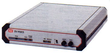
- Integrates voice/fax and data for transmission via a dial-up modem or a digital link
- Adaptive bandwidth allocation optimizes bandwidth utilization
- One or two compressed voice/fax channels plus one synchronous data channel
- TDM, bit-interleaved for low delay
- High quality MPMLQ voice compression at 4.8, 6.4, 7.2, 9.6 or 12.8 kbps
- Automatic voice/fax detection
- In-band fax support for Group III fax
- Supports applications requiring double compression
- Voice interfaces: (A) 2-wire FXS (B) 2-wire FXO (C) 2-wire/4-wire E&M
- Integral support of DC current feed and ring generation for FXS interface
- Link data rates from 9.6 to 256 kbps
- Guaranteed bandwidth allocation for SNA traffic
- Link interfaces:
– V.24/RS-232
– V.35
– V.36/RS-449
– RS-530 (E) X.21 - Configuration downloading to remote unit
- Remote loopback, BER test, tone injection
- Dial-up on demand function for PSTN applications
- Automatic adjustment to fall-back data rate
DESCRIPTION
- DV-MUX3 is an adaptive TDM Multiplexer, integrating one or two voice/fax channels together with one synchronous data channel onto a dial-up modem or digital link.
- The voice channels provide high quality voice compression using the MPMLQ voice digitizing algorithm, at selectable rates of 4.8, 6.4, 7.2, 9.6 or 12.8 kbps. Toll quality voice reproduction (compatible to ADPCM at
32 kbps) is guaranteed when using rates of 6.4, 7.2, 9.6 or 12.8 kbps. - Each compressed voice channel is available with one of the following interfaces (see Ordering):
- 2-wire FXS for direct connection to a telephone set
- 2-wire FXO for connection to a PABX extension line
- 2-wire, 4-wire E&M interface.
- In-band fax support is available for Group III fax machines and complies with T.4 and T.30 standards.
- For applications requiring low delay, such as IBM SNA sessions, DV-MUX3 ensures that the minimal required bandwidth is always available, even in adaptive mode (see Figure 2).
- The synchronous data channel operates at rates up to 252.8 kbps. The actual rate depends on the data rate of the main link, and on whether the operating mode is adaptive or non-adaptive. In the adaptive mode, the bandwidth is allocated to the voice and data channels dynamically, with the data channel receiving additional bandwidth when the voice channel is “idle” (telephone on-hook). In the non-adaptive mode, each channel is allocated a fixed bandwidth.
- Each compressed voice channel is equipped with an integral echo canceller for canceling the near end hybrid echo. The module is also equipped with forward error correction for checking the most vital speech information bits (at 7.2 and 9.6 kbps), thus maintaining voice quality even at a channel bit error rate of 1 x 10⁻³.
- Status indicator LEDs include: transmit and receive data (selectable for link, data or voice channels), sync loss, test and power. The LEDs also provide configuration error indication.
- Diagnostics include remote loopback for each channel, BER test for data channel and tone injection for the voice channels.
- The dial-up mechanism for PSTN applications activates the DTR signal to the modem only if the voice channel is in the “off-hook” state, or if the DTR of the data channel is active.
- Two DV-MUX3 units (1U high each) can fit side-by-side in a 19″ rack.
- DV-MUX3 works only opposite another DV-MUX3 unit (not compatible with DV-MUX or DV-MUX2).
APPLICATIONS
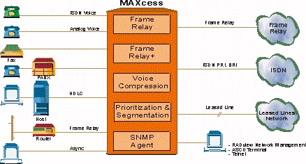
Figure 1. Voice/Fax and LAN Traffic over High Speed WAN Link
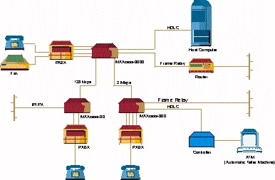
Figure 2. Voice/Fax and SNA Session over Dial-Up Connection
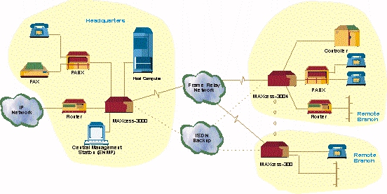
Figure 3. Tandem Application for Remote to Remote Connectivity via Central PABX and Router
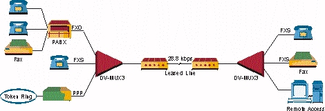
Figure 4. Single Leased Line for two Voice Calls and Data Traffic
ORDERING
- DV-MUX3/V/*/#/+
Multiplexer with single voice channel - DV-MUX3/2V/*/#/+
Multiplexer with two voice channels - *Specify power supply:
100 for 100 VAC supply
115 for 115 VAC supply
230 for 230 VAC supply
48 for 48 VDC supply - #Specify interface for voice channel:
S for 2-wire FXS
O for 2-wire FXO
X for one channel FXS and the other FXO (available only with 2V option)
E for E&M interface - +Specify interface for both link and data channel:
V24 for V.24/RS-232
V36 for V.36/RS-449
530 for RS-530
X21 for X.21
3524 for V.35 link and V.24 data channel
2124 for X.21 link and V.24 data channel
